Gear Structure
The picture shows a dialog window, displaying in upper part the number of gears, the number of wheels and gear structure. All the information is read from the data file or introduced by the user. The structure can be modified. A completely new structure can also be defined by introducing pairs of wheel connections for particular gears, using the bottom part of the dialog window – Define or modify the structure. If a new data file name has been introduced into the Select the folder, data file... dialog window, the new structure needs determining.
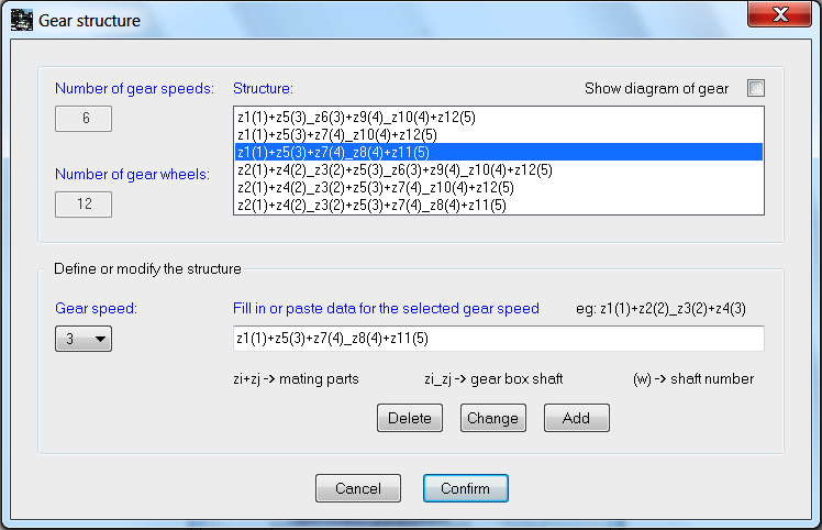
The upper part of the dialog window contains information on the gear structure. If you select a line in the Structure editing field (by clicking on it), there will appear an adequate gear number in the Gear speed field and a sequence of toothed gears in the Fill in data for the selected gear speed field in the bottom, editing part of the dialog window. Similarly, selecting a gear in the Gear speed field, a structure entry for a chosen gear is displayed in the Fill in data for a selected gear speed box. Here, you can modify a pair of a chosen gear and introduce it into the gear structure using the Change button or remove the chosen gear by clicking Delete.
When the field Show the gear diagram is indicated, the focus is on the schematic diagram of the analysed gear, if it exists (exemplary gears or the diagram files indicated at the previous stage).
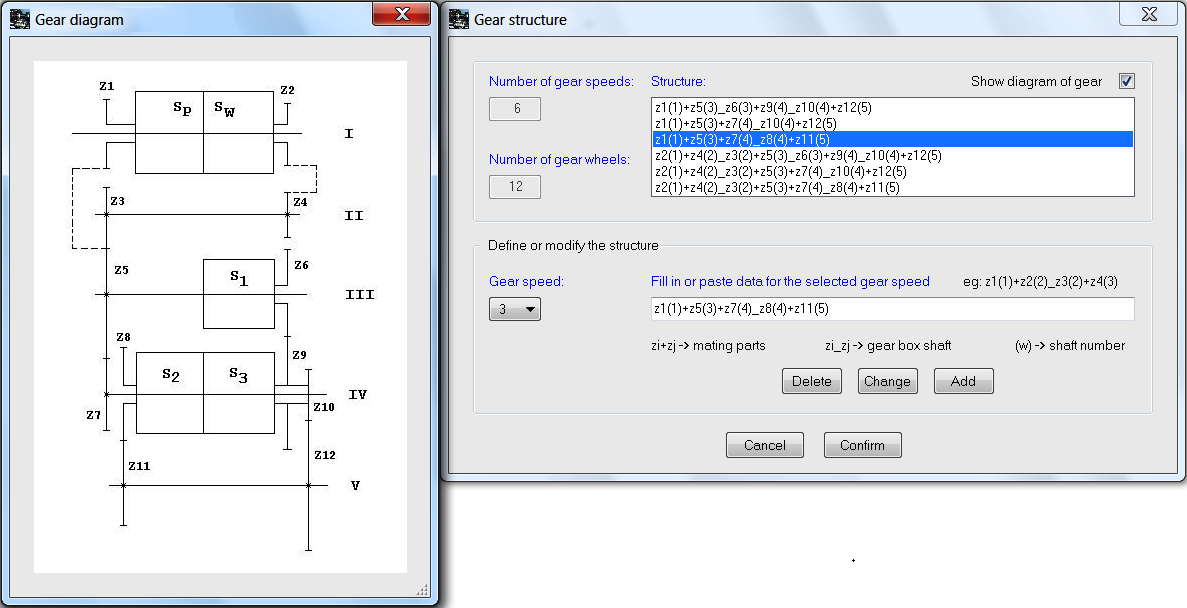
Using the highlighted diagram, particular links in the gear structure can be easily found and correctness of the existing entries of structures verified.
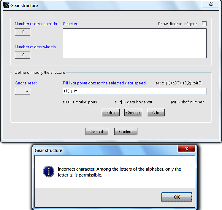
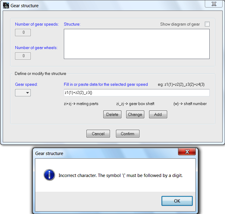
In case of editing a new structure the Structure box is initially empty. A pair of wheels can be typed or moved to the Fill in data for a selected gear speed box. When typing a sequence of wheels for a given gear, use the plus sign '+' between the wheel designates if the wheels cooperate, and the underline sign '_' for the wheels bend with a common shaft. Each wheel description always begins with the ‘z’ sign, for example z1, z5, z12 etc. Additionally, after the symbol of every gear one should to enter shaft number (parenthetic), whereon himself finds. While introducing wheel pairs for a chosen gear, the number of the edited gear appears in the Gear speed box. On completion of the structure description for a particular gear, don’t press keyboard ‘Enter’ button, select the Add button, which will put the gear into the gear structure (the Structure).
The entering of links of the new structure is monitored on an online basis. In the case of incorrect entries, warning notes will appear, for example:
or
When the key Cancel in the window Gear structure is selected, we return to the dialogue window Status of the project and the data relating to the data structure will not be accepted. Whereas, clicking Confirm accepts the structure data and opens the Status of the project dialog window.
In the program one placed example files with data for the ‘power shift’ gearbox, shown below:
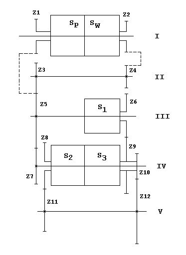
recording of the gear structure:
z1(1)+z5(3)_z6(3)+z9(4)_z10(4)+z12(5)
z1(1)+z5(3)+z7(4)_z10(4)+z12(5)
z1(1)+z5(3)+z7(4)_z8(4)+z11(5)
z2(1)+z4(2)_z3(2)+z5(3)_z6(3)+z9(4)_z10(4)+z12(5)
z2(1)+z4(2)_z3(2)+z5(3)+z7(4)_z10(4)+z12(5)
z2(1)+z4(2)_z3(2)+z5(3)+z7(4)_z8(4)+z11(5)
and for the classical gearbox:
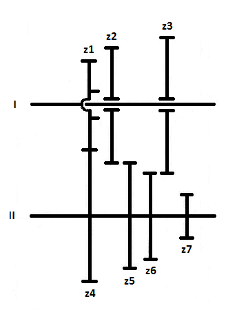
recording of the gear structure:
z1(1)+z4(2)_z6(2)+z3(1)
z1(1)+z4(2)_z5(2)+z2(1)
z1(1)+z4(2)_z7(2)+z8(3)
where (3) - shaft of the back running wheel z8, the shaft and the wheel z8 are not shown in this diagram